Acorn A4 Laptop
CMOS Battery Replacement
The CMOS battery in your A4 Laptop will not last forever, It will leak sooner or later,
due to age or lack of charge. So this section will deal with fitting a replacement cell.
The original cell fitted to the A4 is a VARTA 1V2 Nicad, this is a tagged button cell of 1.2v
and an 11 mAh rating. The battery is obsolete! and VARTA UK do not have any left.
I have found Farnell can supply a suitable cell, it is 1.2v but has a slightly higher mAh
and larger tags, so I have re-located the cell to avoid modifying and possibly damaging the tags.
Looking at the old cell, Acorn modified the tags to. So, here we go with the A4 cell replacement.
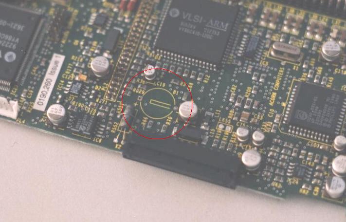
In this view I have already removed the cell from the PCB.
See my A4 Hard Drive Repair page for details on stripping down the A4.
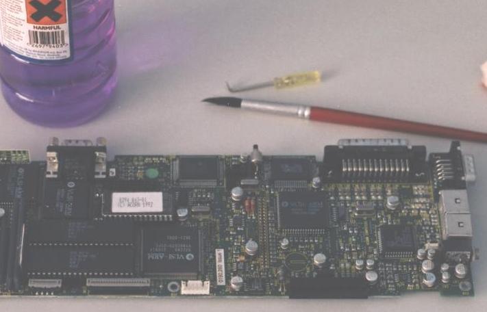
Battery Acid is Dangerous, so take care! Here I am washing the PCB with Methelayted Spirit
to remove any spilt acid from the PCB and any other affected components.
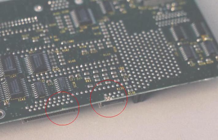
On the underside of the PCB I also found two areas of track damage. It looks like it has been
this way since initial assembly by Acorn's sub-con's A bit of Quality Control missing I think.
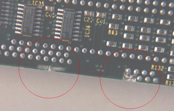
Here I have used a sharp tool, a craft knife will do, to scrape back the PCB's laquer to expose
the good copper on the undamaged parts of the track. The other area of damage I left as not critical.
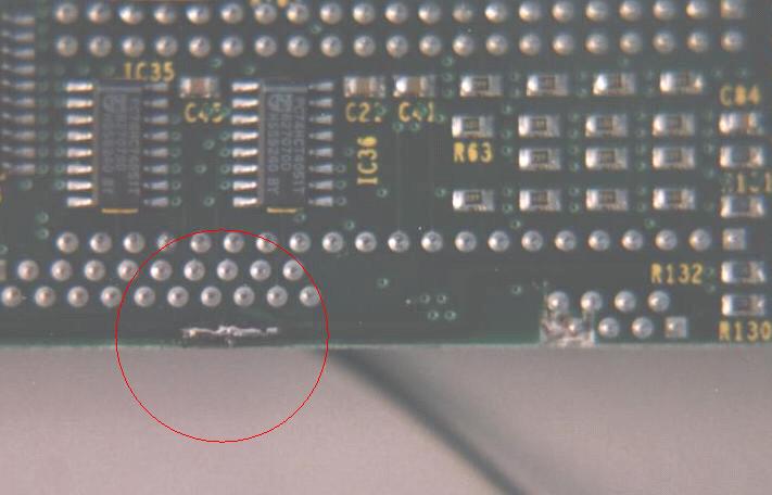
I have now bridged the gap in the track with solder. I have also made sure that the solder bridge is
as thin as possible, so not to add any undue resistance to the circuit involved.
I then painted some clear laquer onto the repair so that the new joint will be insulated.
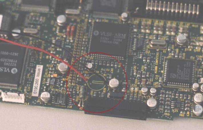
I have now attatched two fly leads to the old cell's PCB mounting points.
I cannot fit my new cell here due to clearance issues. Therefore,
I am re-locating to a clear area, as short a distance away as possible.
I have used single strand wire so that I can form it easily to go round existing components.
It will also hold its shape and not lift away from the PCB if the machine is knocked.
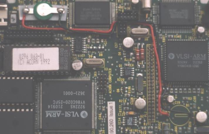
The cell is stuck to the top of another IC witha double sided sticky pad. This location allows me
to keep an eye on the cells condition and spot any future leaks well in advance.
NOTE the POLARITY of the cell when connecting.
Also use a hot iron for a very short time when soldering to avoid cell damage.
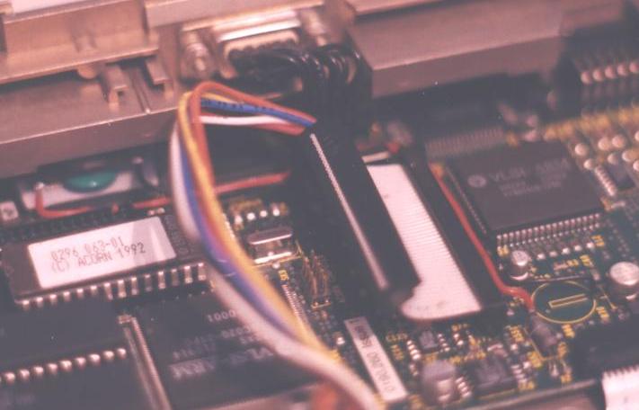
This last view shows the cell in position with the PCB back in the case.
There is very little room inside the A4 and this was the optimum location for the cell.
If you have arrived here from a Search Engine
Click the link below to go to the Classic Acorn Home Page
Everyone else use the Navigation Section on the Left
<---------------------------------------------------
|
|