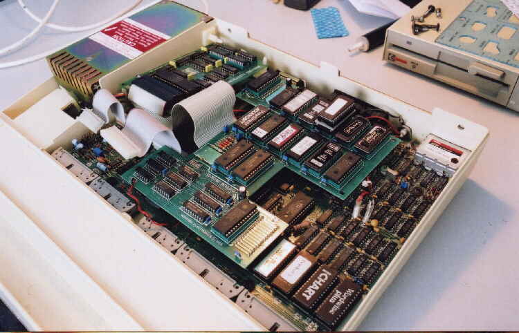
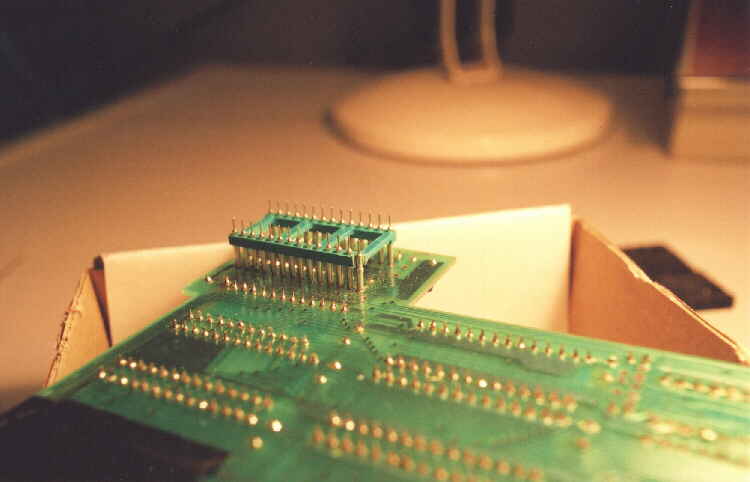
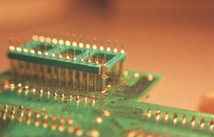
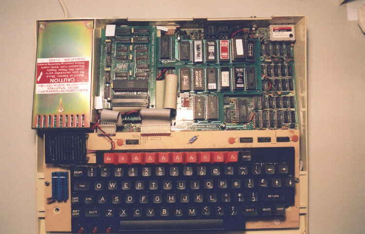
But alas the image above shows that even though the repair worked fine "electrically" the gain
in "height" of the ROM board by approximately 4mm prevented my fixing the keyboard back in place.
I'm now resigned to "fixing" the original pins so as to keep the boards original height in the case.
Firstly remove previous attempt at repair. Using the edge of a "needle-file" again,
I sawed my way into the header plug at two points 90 degrees apart as to expose the broken pin.
Then using the edge of the file, saw through the broken pin right below the plastic strengthener to chop off the top.
Use EXTREEM CARE! when doing this. Very light pressure on the file and relatively quick strokes.
The material is Brass so will cut easily, BUT! when you start to break through the bottom pin will try to bend.
Also be careful not to damage any tracks on the PCB. So be patient!! time taken saves more damage.
Next de-solder the remaining part of the pin from the board and SAVE IT! .
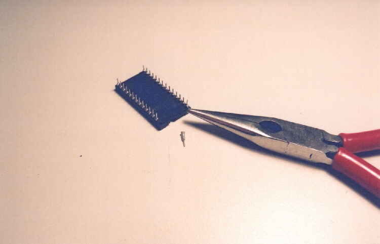
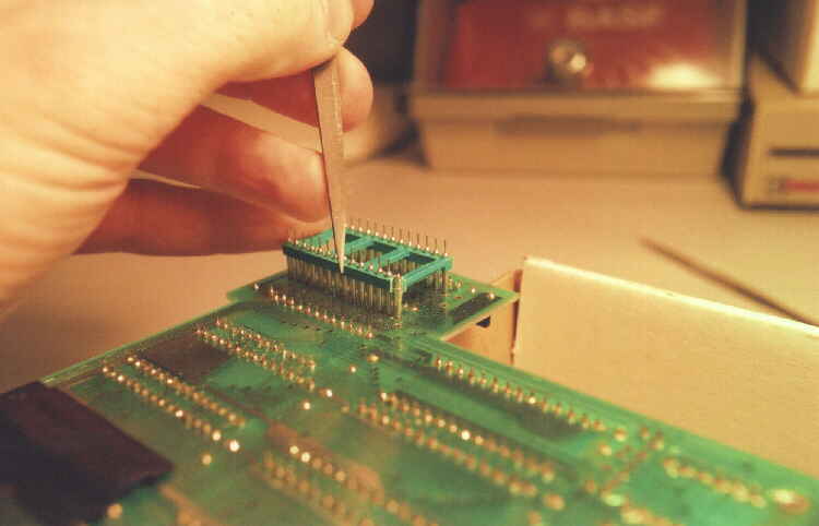
Find a spare 26pin Dil socket. It has to be one with "round" pins. Using a pair of "long-nose" pliers,
carefully grip a pin and push "down" to pop it from the plastic holder.
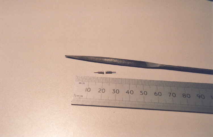
Lay this and the freshly de-soldered pin end to end. Then if needed, file the original pins thicker end shorter
to give a dimension where the original pin butts up to the board to the tip on the new pin of 13mm.
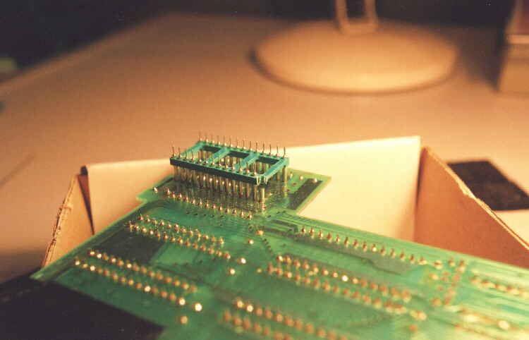
Re-solder the original pin to the board, then place the "new" pin on top of it.
Very carefuly solder the two parts together. NOTE!! as you solder these together the original pin will more than
likely move as heat travels down the pin. Time and patience will see you through, but try not to overheat anything.
Take a break for things to cool then go again.
Finally repeat this process for the header the other end of the board, or for any other pins broken.
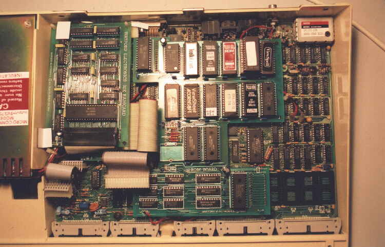
Re-fit the board to the Beeb again, being very careful to locate the pins into the ANALOGUE and OS sockets.
This time the board fits at the correct height allowing the keyboard to be bolted back into place.
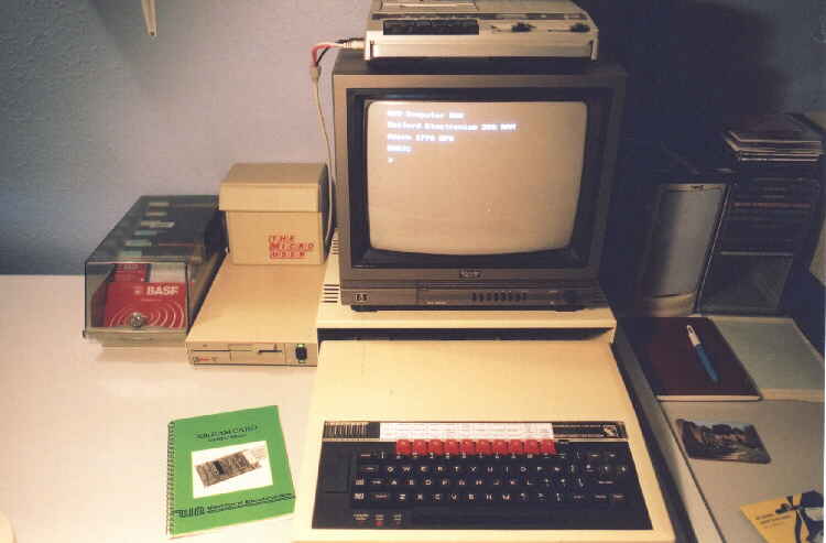
Fire it up! Blahhhh Beeeep Startup Message, Job Well Done.